

Introduced in 2018, the Klotz DX10 passive direct box offers very attractive features at a modest price (on average, just under 150 euros), given its overall manufacturing quality and that of its transformer, an essential element of a passive direct box.
Earlier this year at the ISE, we decided during our meeting at the Klotz stand with Frédéric Kromberg (Sales Manager) and Claude Blanc (who is in charge of the French subsidiary), to present it to you in depth.
After a series of measurements performed in various representative configurations of its use in our lab, we turned it over to some sound engineers in the field to gather their impressions and those of musicians on tour over a period of several months. Here are the results of our research.
Présentation
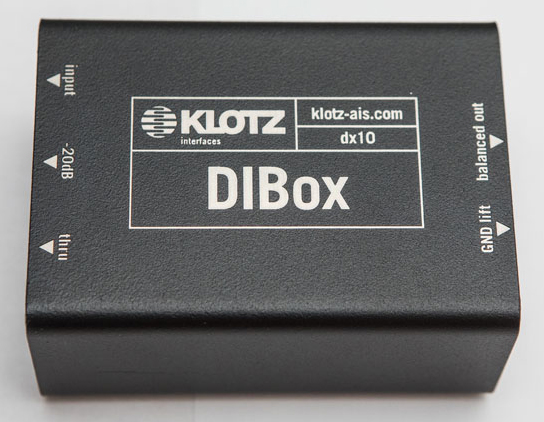
The Klotz DX10 is housed in a compact, double u-shaped 2 mm sheet-steel enclosure covered with an ultra-resistant finish, to withstand the rigors of the stage.
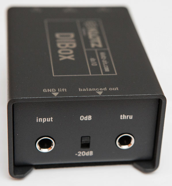
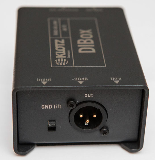
No frills on this model, just a 6.35″ jack connector (for throughput to an amplifier) in addition to the input jack and the XLR3 male output connector, and two switches: one for the pad (20 dB attenuation) and one for the ground-lift on the output side that uncouples pin 1 of the XLR from the output ground (via an R-C network).
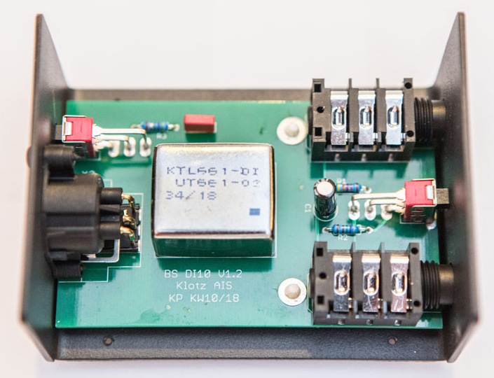
For example, there is no polarity (phase) inverter as on some models, which is superfluous, in our opinion, as all preamps, consoles, stage racks and other equipment are equipped with it. Since this is a passive DI box, there is no need for a battery or even for phantom power through the balanced line. Everything obviously depends on the quality of the audio transformer used and, as we will see later, Klotz has done things right.
A little refresher
The main function of a direct box is to connect a medium- or high-impedance output source in an unbalanced connection, usually an instrument – electric guitar, bass, acoustic guitar, keyboard, etc. – to a balanced low-impedance mic/line input of a preamplifier or console.
There are completely passive models (such as the DX10) that use a transformer, fully active models (solid-state or tube), which unfortunately do not allow galvanic isolation between source and preamplifier, and there are also active hybrid models that use an isolation transformer that, if properly designed, are the best choice but also the most expensive.
Active models, of course, require a power source, whether it is from batteries (with voltage converters) and/or phantom power via the pre-amplifier’s phantom supply.
In any case, even if the input impedance of the DI is high and can accommodate sources with an output impedance of 5 to 25 kΩ (some guitars) without too much attenuation, we mustn’t forget that an instrument cable (especially a high quality one with an electrostatic sheath) has a linear capacity in the order of 100 pF/m, which represents a capacitive load of 500 pF at a length of 5 m and this, in combination with an output impedance of 20 kΩ, constitutes a low-pass filter that cuts at 14.5 kHz (at -3 dB with a 1st order slope – still tolerable for a bass).
In other words, with long cable lengths, you can say goodbye to any high frequency signal transmission, not to mention that with an unbalanced high-Z lead, the longer it is, the more it picks up ambient electromagnetic disturbances (and there are many on a stage), especially at low frequencies. Therefore, it is preferable not to exceed 5 m between the instrument and the DI, with 3 m being a good length.
Our measurements
The turn ratio of the transformer used in the DX10 is 1:12 (Np/Ns=12) as evidenced by the gain of -21.58 dB (20 log(1/12)) at low source impedance.
This is the ratio adopted on the vast majority of leading high-quality transformer manufacturers (such as Jensen – now Radial Engineering, Cinemag or Lundahl) for this application. It is a good compromise for obtaining a high input impedance with a balanced load impedance of around 1.5 kΩ, while achieving a very high primary magnetizing inductance and a reasonable leakage inductance in a shielded transformer with electrostatic screens between the primary and secondary coils.
With a ratio of 1:12 between coils, the reflected impedance on the input side is multiplied by 144 (122), which makes it possible to support source impedances up to about 30 kΩ without too much attenuation or other disturbance. This is suitable for all types of instruments, even guitars with passive circuits and high output impedance.
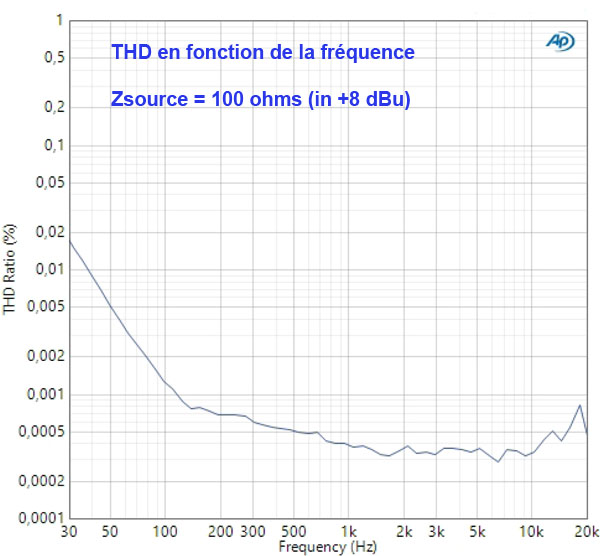
The first pleasant surprise we encountered during the measurements was the very low distortion levels, especially in the low frequencies (this is the weak point of all but the highest quality transformers). By driving the DX10 at low impedance (100 ohms) at +6 dBu with a balanced load of 600 ohms at the output, we obtained the following THD readings:
- 0,0095 % at 31 Hz
- 0,0013 % at 100 Hz
- 0,00038 % at 1 kHz
- et 0,00036 % at 10 kHz
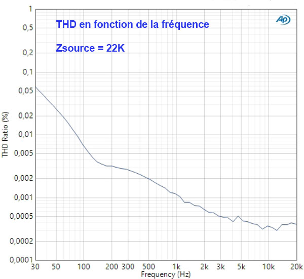
This was performed with a test band of 80 kHz, in order to take into account all harmonics. Under the same conditions, the intermodulation distortion (according to the SMPTE standard) is around 0.0012%. This is remarkable performance that does not significantly degrade when the impedance is 22 kΩ. This is illustrated in Figures 1 and 2, which show the THD as a function of frequency, at an input level of +8 dBu (2 Vrms), respectively with a source impedance of 100 Ω and 22 kΩ.
This transformer designed by Klotz competes with the best, with very high self-magnetization of the order of 1000 H (according to the unloaded input impedance measurements) and a very narrow hysteresis window, which only generates odd-series distortion harmonics, as it should in a good transformer.
To corroborate our observations, we show in Figure 3 the measurement of the first 10 harmonics for a fundamental at 1 kHz at a level of +8 dBu and a source impedance of 22 kΩ.

You can see that the 3rd and 5th harmonics are predominant, while the others are, on average, down to -125 dB. On this point, if we were to observe a rise in even-series harmonics, this would mean that the transformer was “magnetized”, i.e. subjected to a direct current at the input, which offsets the field induction curve; this is impossible on the DX10 since there is a junction capacitor of 10 μF.
This indicates that, even with a high source impedance, the distortion does not increase too much. In general, the best results are obtained with an impedance that represents between 1/5 and 1/10 of the series resistance of the input winding, i.e. less than 1 kΩ.
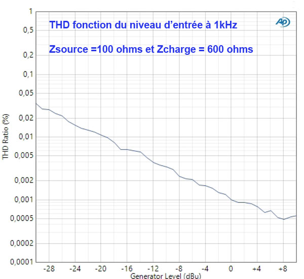
To conclude on THD, Figure 4 shows the evolution of the harmonic distortion with respect to the level fed into the input. This shows that the appropriate operating range corresponds to levels between -20 dBu and +10 dBu, which corresponds well to instrument output levels.
At 1% THD, the maximum admissible level is +21 dBu (very good) and therefore theoretically +41 dBu with the Pad (-20 dB) switched on, but since the coupling capacitor is a 35 V model, we would rather say +32 dBu, which means that it can be connected to the instrument amplifier’s output without problems.
Figures 5 and 6 plot the frequency response curve, with a low and a high source impedance, respectively. In the worst case, the high cut-off frequency is above 30 kHz at -3 dB, which is more than acceptable. Figure 5 (70 kHz cut-off) shows a very slight peak (+1 dB !) at the end of the band due to the leakage inductance of the transformer.
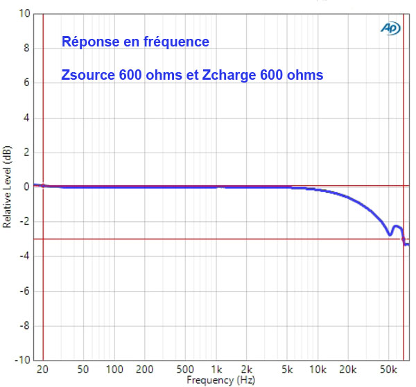
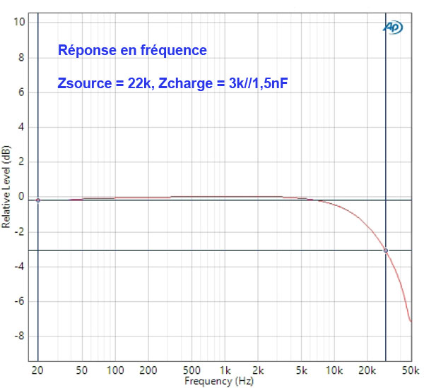
In addition to a magnetic shielding made of high-permeability material (mumetal type), the latter uses two electrostatic shields between the primary and secondary coils to reduce inter-winding and winding-to-ground capacitance. Inevitably, even with “high-end” winding techniques, this affects the coupling and therefore the leakage between the primary and secondary.
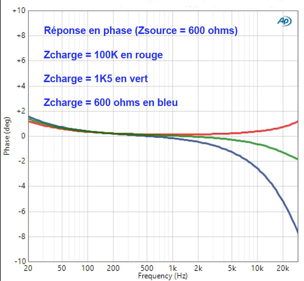
In Figure 7, we show the phase response with different balanced output loads. Once again, depending on the load, the response at the top of the band is affected by the leakage inductance.
With the normal load of an average preamp and 20 to 30 meters of microphone cable, this corresponds to the green curve and results in a phase deviation of +/-1.5° between 20 Hz and 20 kHz, which is very good.
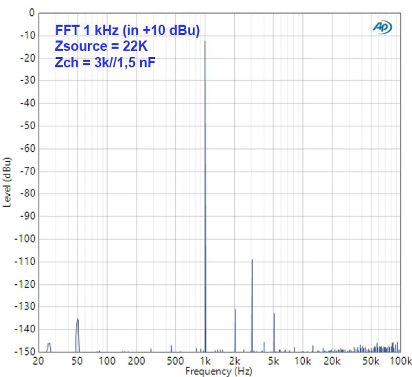
Figure 8 shows a fast Fourier transform of the response to a sine wave at 1 kHz, to reveal both the background noise and the distribution of the harmonics. This is, again, very good: except for the 3rd harmonic, the background noise (50 Hz in particular) and the other lines are at a level of less than -120 dB.

Finally, in Figure 9, we can see the response with a square wave signal at low and high source impedance (same output load: 3 kΩ and 25 m of cable).
Apart from normal attenuation with the high source impedance, the squares are very well reproduced, with minimal over-oscillation and clean edges.
Some remarks and suggestions
Although positively impressed by the overall performance obtained for a relatively modest price, we nevertheless have some suggestions to make, which are certainly more a matter of purism than an absolute necessity:
– As electronic engineers fairly attuned to the design of audio products, we would have chosen a film capacitor (polypropylene or polyester) for the obligatory input decoupling capacitor (10 μF, unpolarized) instead of an unpolarized electrochemical type (actually two polarized ones in a head-to-tail series arrangement internally). The quality over time (and the distortion) is not the same (but the cost is not the same either, of course).
– The leakage inductance of the transformer – which is inevitable, especially since it includes a double electrostatic screen to improve the common mode rejection – necessarily induces a more or less significant “peaking” at the high frequencies, depending on the damping of the resulting second-order circuit and, therefore, on the connected load impedance (the balanced input impedance of the preamplifier).
In our opinion, this is what the sound engineers and musicians who tested the DX10 live found in practice at the upper end of the spectrum (see below). The optimum transmission length (according to measurements) is about 20/30 m with microphone cable and a balanced impedance of between 1.2 and 3 kΩ, with 3 kΩ providing the best frequency and phase response.
– The common mode rejection is fine (75 dB at 50 Hz and 50 dB in the middle of the band), better than that of active DI boxes, but 10 or 15 dB below the best (with transformer, of course).
Feedback from the field
After looking at the numbers, let’s move on to the ears, and there are none more appropriate than those of monitor and FoH sound engineers and, especially, bass players – a prime target for a DI – such low-frequency, dynamic and high impedance sources do not usually mix well with transformers, however good they may be.
Alex Maggi was up for it, and not just him, as you’ll soon see. For a few months he was entrusted with the DX10 that was used for the measurements so that he could test it on the last dates of the Christophe Willem tour, on which he was responsible for the monitors.
Alex Maggi : tried it at Biscarrosse during the soundcheck by comparing it to the classic Canadian active DI box we use, and we got into the subjective. It had some good and some bad, we couldn’t really distinguish them.
So we decided to use it that very evening and, unanimously, Julien Martin, who was at FoH, Nils Thomas , Willem’s bass player, and I at the monitors all found that the bass sound was much better positioned in the mix, it cut through much better. We were pretty thrilled. At the end of the tour, Nils went home with the DI.
SLU : Does he have a studio?
Alex Maggi : Yes, he does. And more importantly, he likes technology and does tests by recording and comparing several configurations of a higher price and he was surprised by the results.
Then Julien Martin picked it up and took it on the Gims tour, where he mixes the monitors, and made Boom (Franck Jean, alias BOOM, the bassist and musical director of Gims) try it out. He, too, thought it was very good. For this tour he uses an American DI/preamp with tubes.
After the test, he changed the settings of his DI/preamp to a lower level in order to get closer to what he heard with the Klotz (laughs). A comment that keeps coming up is that the bass is very precise, natural and very musical. Realistic, in a way.
SLU : And in the high end of the spectrum?
Alex Maggi : It’s a matter of taste. There are those who prefer a vacuum tube or the Jensen transformer, those who find that it lacks a little treble, unlike for the bass, where it is unanimously approved. In any case, a passive DI at this price that works so well is very interesting and it will increase the selection against the two most commonly used active standard models.
You know how much I hate technical things. Oscilloscopes and all don’t interest me, I would prefer a blind a test thousand times more. I never look at the numbers. I listen, I compare and I choose. In a blind test, the Klotz is at least equal to the “reference” models in the market.
A very big thank you to Alex, Julien, Nils and Boom for their ears and 10 fingers.
Conclusion
The Klotz DX10 is a high quality, robust and straightforward product, at a low price, which should fully satisfy its owner, and is perfectly suited for the stage, especially for bass guitars.
 What we like:
- The performance and sound
- The simplicity of a passive DI
- The durability
- The quality/price ratio
 What we don’t like:
- Not a big deal, but: the slightly weak common mode rejection
And more informations on the Klotz website


